


Abstract
In the era of highly automated and efficiency-driven electronics manufacturing, a tiny surface-mount component undergoes a precise and reliable journey from production to accurate placement on a PCB. The tape and reel machine serves as an indispensable “organizer” and “enabler” in this journey. This article provides a comprehensive guide to tape and reel machines, exploring their working principles, core components, different types, key selection criteria, applications, and future development trends. Whether you are a newcomer to electronics manufacturing or an experienced engineer seeking deeper understanding, this article delivers a panoramic and in-depth analysis of this critical equipment.
Table of Contents
Chapter 1: Introduction – The Invisible Hero of Automation
1.1 Microcomponents, Major Challenges: Feeding Dilemmas on SMT Lines
1.2 What is a Tape and Reel Machine? Definition and Basic Concepts
1.3 Historical Evolution: From Manual to Fully Automated
Chapter 2: In-Depth Analysis: Working Principles and Core Components of Tape and Reel Machines
2.1 System Overview: A Highly Coordinated Workflow
2.2 “Heart” Component – Pick-and-Place Head: Technological Evolution and Types
2.3 “Skeleton” and “Nerves” – Material Handling and Transport Systems
2.4 “Eyes” and “Brain” – Vision Inspection and Motion Control Systems
2.5 “Outerwear” and “Home” – Carrier Tape, Cover Tape, and Reel Systems
2.5.1 Carrier Tape Types and Specifications
2.5.2 Cover Tape Selection and Heat Sealing Principles
2.5.3 Reel Standards and Drive Mechanisms
Chapter 3: Types of Tape and Reel Machines and Selection Guide
3.1 By Automation Level: Manual, Semi-Automatic, Fully Automatic
3.2 By Component Type: Standard, Special-Shaped, Wafer-Level Packaging
3.3 By Speed and Capacity: Entry-Level, Mid-Range, High-Performance
3.4 Key Selection Criteria: Throughput, Precision, Flexibility, Total Cost of Ownership
Chapter 4: Applications and Value of Tape and Reel Machines
4.1 Core Battlefield: Surface Mount Technology Industry
4.2 Extended Applications: Semiconductor Packaging and Testing
4.3 Special Scenarios: Automotive Electronics, Medical Devices, Aerospace
4.4 Quantified Value: Efficiency, Quality Assurance, Cost Reduction, Traceability
Chapter 5: Operation, Programming, and Maintenance for Long-Term Stability
5.1 Detailed Standard Operating Procedures
5.2 Programming Basics: Recipe Management and Parameter Optimization
5.3 Daily Maintenance and Preventive Care
5.4 Common Fault Diagnosis and Troubleshooting Tips
Chapter 6: Challenges, Limitations, and Future Trends
6.1 Current Technical Challenges and Limitations
6.2 Micro Miniaturization and High-Density Challenges
6.3 Integration with Industry 4.0: IoT, Big Data, and Digital Twins
6.4 Flexible Manufacturing and Quick Changeover Requirements
6.5 New Materials and Sustainability
Chapter 7: Conclusion
Appendix: Glossary of Common Terms
Chapter 1: Introduction – The Invisible Hero of Automation
1.1 Microcomponents, Major Challenges: Feeding Dilemmas on SMT Lines
Imagine the motherboard of a modern smartphone, densely packed with hundreds of tiny resistors, capacitors, inductors, and integrated circuits. These surface-mount devices (SMDs) can be as small as 0.4mm x 0.2mm (0201 size) or even smaller. On an SMT production line, high-speed pick-and-place machines place these components at tens of thousands of points per hour.
A fundamental question arises: how can tens of thousands of tiny components be supplied to pick-and-place machines in a stable, reliable, and high-speed manner? Manual feeding is clearly insufficient. The answer lies in standardized packaging—carrier tape. And the machine that converts bulk components into standardized taped packaging is the tape and reel machine.
1.2 What is a Tape and Reel Machine? Definition and Basic Concepts
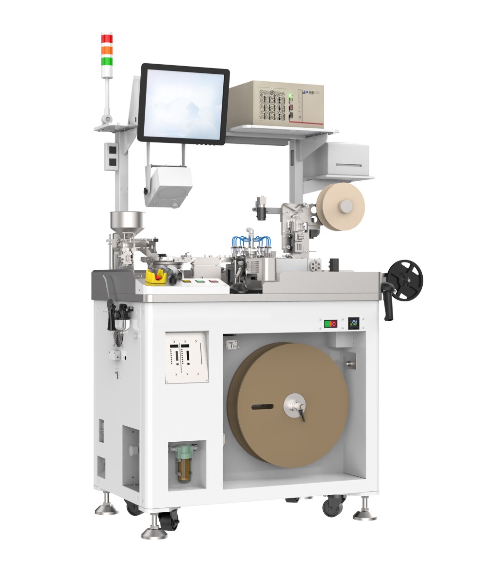
A tape and reel machine is an automated or semi-automated production device. Its core function is to pick bulk, tube, or tray-packaged components and place them into the pockets of a carrier tape according to a predefined orientation. Then, a cover tape is applied and heat-sealed, and the taped components are wound onto a reel. The resulting reel can be directly fed into an SMT pick-and-place machine.
Essentially, it bridges the gap between component production and assembly automation. Without it, high efficiency and precision in modern electronics manufacturing would be impossible.
1.3 Historical Evolution: From Manual to Fully Automated
Early electronic components were larger and could be manually or lightly automated using vibration feeders. With shrinking component sizes and increasing production volumes, manual operation became inefficient and risky due to static electricity and handling damage.
In the 1970s and 1980s, semi-automatic tape and reel machines emerged with mechanical positioning and pneumatic control, significantly improving consistency and efficiency. In the 21st century, the advent of machine vision, high-precision servo drives, and computer control led to modern fully automated high-speed tape and reel machines capable of handling micron-scale components with remarkable speed and accuracy, becoming essential in electronics manufacturing.
Chapter 2: In-Depth Analysis: Working Principles and Core Components
2.1 System Overview: A Highly Coordinated Workflow
A typical fully automated tape and reel machine workflow:
- Feeding: Bulk components are loaded into a vibratory feeder or trays are loaded into the machine.
- Orientation and Queuing: Vibratory feeder arranges components in a uniform orientation and conveys them to the track.
- Picking: High-precision pick-and-place head picks components from the track end.
- Inspection: Vision system inspects components for appearance, polarity, and size, and corrects position/angle.
- Placement: Pick-and-place head accurately places components into moving carrier tape pockets.
- Covering and Heat Sealing: Cover tape is applied and heat-sealed onto the carrier tape.
- Reeling: Sealed tape is wound onto the reel under controlled tension.
- Monitoring and Data Logging: The control system tracks production quantity, yield, and errors.
2.2 “Heart” Component – Pick-and-Place Head
The pick-and-place head determines machine speed and accuracy. Key technologies:
- Pneumatic: Simple and cost-effective, limited in speed and precision.
- Servo-driven: Mainstream today; high-resolution encoder-controlled servo motors provide precise positioning, smoother motion, and longer lifespan.
- Linear Motor-driven: High-end machines use contactless linear motors for ultra-high speed and minimal wear.
Heads use vacuum nozzles for component pickup, with interchangeable sizes for different parts. Some models include pressure sensors to ensure successful pickup.
2.3 “Skeleton” and “Nerves” – Material Handling and Transport Systems
- Vibratory Feeders: Arrange bulk components along spiral tracks using piezo or electromagnetic vibrations.
- Tray Feeders: For delicate or irregular components that cannot use vibration feeders.
- Carrier Tape Transport: Servo-driven chain mechanism ensures accurate tape advancement matching pocket spacing.
2.4 “Eyes” and “Brain” – Vision and Motion Control Systems
- Vision System: High-resolution CCD or CMOS cameras inspect components for defects and polarity, and calculate X, Y, θ offsets for placement correction.
- Motion Control System: Industrial PLC or PC-based controllers coordinate servo motors, pneumatic actuators, and I/O modules for synchronized operation.
2.5 “Outerwear” and “Home” – Carrier Tape, Cover Tape, and Reel Systems
2.5.1 Carrier Tape Types and Specifications
Manufactured according to EIA-481 standards, pocket pitches include 2mm, 4mm, 8mm, 12mm, 16mm, 24mm, 32mm, 44mm.
- Plastic Tape: Most common, available in conductive, antistatic, or insulating types.
- Paper Tape: Low cost, moisture-sensitive, lower precision and strength.
2.5.2 Cover Tape Selection and Heat Sealing Principles
Cover tape protects components and ensures visibility. Key factors include sealing temperature.
- Transparent: Allows visual inspection.
- ESD-safe: For sensitive components.
Heat sealing uses a patterned heated sealing wheel; temperature and pressure must match tape and cover material.
2.5.3 Reel Standards and Drive Mechanisms
Standard reel sizes: 7-inch, 13-inch. Servo-driven with tension control ensures even, tight winding for transport and handling.
Chapter 3: Types of Tape and Reel Machines and Selection Guide
3.1 By Automation Level
- Manual/Desktop: Operator inserts components; machine covers tape and reels. <1,000 CPH. Suitable for R&D or low volume.
- Semi-Automatic: Operator loads components; machine handles pick, vision correction, placement, and sealing. Medium speed.
- Fully Automatic: Integrates feeders, pick-and-place, inspection, sealing, and reeling. High speed (thousands to tens of thousands CPH).
3.2 By Component Type
- Standard: Resistors, capacitors, transistors.
- Special-Shaped: Connectors, relays, filters—requires custom feeders and pick tools.
- Wafer-Level Packaging: Picks bare dies from wafers for highest integration and complexity.
3.3 By Speed and Capacity
- Entry-Level: <3,000 CPH, simple structure, low cost.
- Mid-Range: 3,000–10,000 CPH, good precision and stability.
- High-Performance: >10,000 CPH (up to 30,000+), multi-head, linear motors, for mass production.
3.4 Key Selection Criteria
- Throughput Requirements
- Component Types and Packaging
- Precision Needs
- Flexibility / Changeover Time
- Total Cost of Ownership (equipment, consumables, energy, maintenance, labor, footprint)
Chapter 4: Applications and Value of Tape and Reel Machines
4.1 Core Battlefield: SMT Industry
Essential for almost all SMT-fed components.
4.2 Extended Applications: Semiconductor Packaging and Testing
Tape reels facilitate automated testing, marking, and shipping.
4.3 Special Scenarios: Automotive, Medical, Aerospace
High reliability and traceability requirements; tape packaging protects components and supports traceability via markings.
4.4 Quantified Value
- Efficiency: Tens or hundreds of times faster than manual, 24/7 operation.
- Quality: Vision inspection and precise placement reduce human error.
- Cost Reduction: Long-term savings outweigh equipment investment.
- Traceability: Supports smart manufacturing and quality tracking.
Chapter 5: Operation, Programming, and Maintenance
5.1 Standard Operating Procedures
Machine startup, tape and cover tape installation, feeder setup, recipe call-up, production start, monitoring, and reel change.
5.2 Programming Basics: Recipe Management
Graphical interfaces store component parameters:
- Dimensions and thickness
- Pickup coordinates and height
- Vision inspection templates and tolerances
- Heat seal temperature, pressure, speed
- Tape advancement distance
5.3 Daily Maintenance and Preventive Care
- Daily: Clean machine and camera lens, check air pressure
- Weekly: Clean nozzles, filters, check transmission parts
- Monthly/Quarterly: Lubricate motion parts, check servo, calibrate vision system
5.4 Common Fault Diagnosis
- Pickup errors: nozzle clog/wear, insufficient vacuum, component sticking
- Vision inspection failure: lighting, lens dirt, parameter issues
- Placement errors: mechanical or calibration deviation
- Poor sealing: wrong temperature/pressure, worn sealing wheel, material mismatch
Chapter 6: Challenges, Limitations, and Future Trends
6.1 Current Challenges and Limitations
- Miniaturization to 01005 or smaller
- Adaptability to irregular or fragile components
- High initial investment
6.2 Micro Miniaturization and High-Density Challenges
- Ultra-high-resolution vision systems
- Nano-level motion platforms
- Micro non-contact pick tools (e.g., van der Waals micro-grippers)
6.3 Integration with Industry 4.0
- IoT: real-time machine monitoring and OEE
- Big Data & Predictive Maintenance
- Digital Twins for virtual simulation and optimization
- AI vision for defect self-learning
6.4 Flexible Manufacturing and Quick Changeover
- One-touch recipe change via RFID/QR code
- Modular design for quick feeder and pick head swaps
6.5 New Materials and Sustainability
- Biodegradable/recyclable carrier and cover tapes
- Energy-efficient motors and power management
Chapter 7: Conclusion
The tape and reel machine, quietly operating behind the scenes, is a linchpin in digital-era electronics manufacturing. It organizes chaos, consolidates tiny components into massive productivity, and bridges automated assembly lines. From simple pneumatic machines to today’s high-tech integration of optics, mechanics, electronics, computation, and software, its evolution mirrors industrial automation itself. With ongoing miniaturization, customization, and intelligent manufacturing, tape and reel technology will continue evolving with greater speed, intelligence, and flexibility, underpinning the global electronics industry.
Acknowledgements and Outlook
This article is dedicated to engineers, technicians, and industry professionals striving to advance electronics manufacturing in China and worldwide. Technological progress is endless, and discussion on tape and reel machines will continue. We look forward to witnessing more disruptive innovations that further propel this critical field.
Copyright Statement
The content is for reference and educational purposes only. Unauthorized commercial use is prohibited. Technical descriptions may update with advancing technology; please refer to the latest official information from equipment manufacturers.
Appendix: Glossary of Common Terms
- CPH: Cycles per hour, indicating tape machine speed
- SMD: Surface-mount device
- SMT: Surface-mount technology
- Feeder: Component feeder
- Nozzle: Pick-up nozzle
- Vision System: Component inspection system
- Pitch: Pocket center-to-center distance on tape
- Carrier Tape: Tape holding components
- Cover Tape: Tape covering components
- Reel: Tape reel
- Pick & Place: Pick and place operation
- EIA: Electronic Industries Alliance
- OEE: Overall Equipment Effectiveness


留下评论